
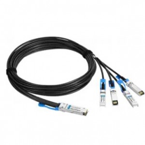
The QSFP+ passive cable assemblies are high performance, cost effective I/O solutions for 40G Ethernet. QSFP+ copper cables allow hardware manufactures to achieve high port density, configurability and utilization at a very low cost and reduced power budget.

PRODUCT FEATURES
•Up to 40Gbps total bandwidth
•4 independent duplex channels 10Gbps
•Up to 7meter transmission
•Infiniband QDR
•QSFP+ interface compliant with SFF-8436
•SFP+ interface compliant with SFF-8472
•Temperature Range: 0~ 70 °C
•RoHS compliant
APPLICATIONS
•40G Ethernet
•InfiniBand QDR
•Networked storage systems
•Hubs, Switches, Routers, Servers
PRODUCT DESCRIPTION
The QSFP+ passive cable assemblies are high performance, cost effective I/O solutions for 40G Ethernet. QSFP+ copper cables allow hardware manufactures to achieve high port density, configurability and utilization at a very low cost and reduced power budget.
Ordering Information
|
Part Number |
Description |
|
QP4X-DP0.5M30WG |
40G QSFP+ to 4SFP+ 10G DAC passive cable 0.5m |
|
QP4X-DP01M30WG |
40G QSFP+ to 4SFP+ 10G DAC passive cable 1m |
|
QP4X-DP02M30WG |
40G QSFP+ to 4SFP+ 10G DAC passive cable 2m |
|
QP4X-DP03M30WG |
40G QSFP+ to 4SFP+ 10G DAC passive cable 3m |
|
QP4X-DP05M26WG |
40G QSFP+ to 4SFP+ 10G DAC passive cable 5m |
|
QP4X-DP07M26WG |
40G QSFP+ to 4SFP+ 10G DAC passive cable 7m |
General Product Characteristics
| Q/4SFP+ DAC Specifications | |
| Number of Lanes | Tx & Rx |
| Channel Data Rate | 10.3125 Gbps |
| Operating Temperature | 0 to + 70°C |
| Storage Temperature | -40 to + 85°C |
| Supply Voltage | 3.3 V nominal |
| Electrical Interface | 38 pins edge connector(QSFP+)
20 pins edge connector(SFP+)
|
| Management Interface | Serial, I2C |
High Speed Characteristics
|
Parameter |
Symbol |
Min |
Typ |
Max |
Units |
Notes |
| Differential Impedance | Zd | 90 | 100 | 110 | ohm | |
|
Differential Input Return Loss |
SDDXX |
<-12+2* SQRT (f) with f in GHz | dB | 0.01~4.1GHz | ||
| <-6.3+13*
Log10/(f/5.5) with f in GHz |
dB |
4.1~11.1GHz |
||||
| Common Mode Output Return Loss |
SCCXX |
< -7+1.6*f with f in GHz | dB | 0.01~2.5GHz | ||
| -3 | dB | 2.5~11.1GHz | ||||
| Difference Waveform Distortion Penalty | dWDPc | 6.75 | dB | |||
| VMA Loss | L | 4.4 | dB | |||
| VMA Loss to Crosstalk Ratio | VCR | 32.5 | dB | |||
Pin Function Definition of QSFP+
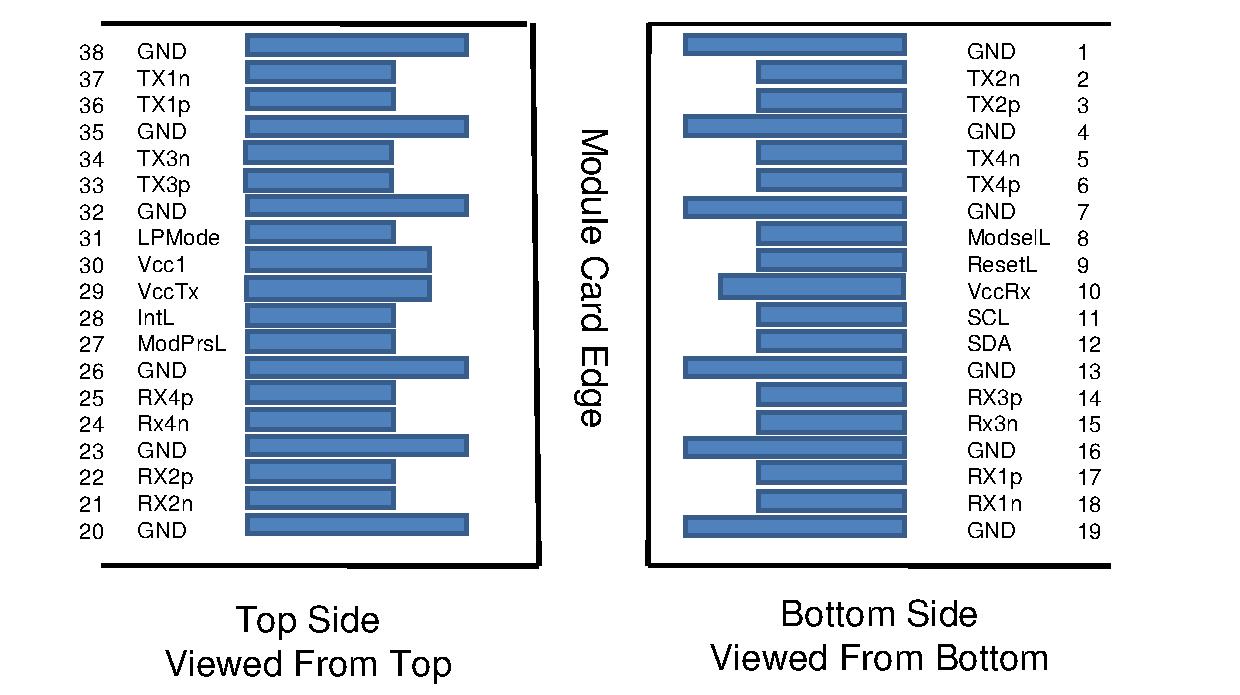
| Pin | Logic | Symbol | Description |
| 1 |
|
GND |
Ground |
| 2 | CML-I | Tx2n |
Transmitter Inverted Data Input |
| 3 | CML-I | Tx2p |
Transmitter Non-Inverted Data Input |
| 4 |
|
GND |
Ground |
| 5 | CML-I | Tx4n |
Transmitter Inverted Data Input |
| 6 | CML-I | Tx4p |
Transmitter Non-Inverted Data Input |
| 7 |
|
GND |
Ground |
| 8 | LVTTL-I | ModSelL |
Module Select |
| 9 | LVTTL-I | ResetL |
Module Reset |
| 10 |
|
Vcc Rx |
+3.3V Power Supply Receiver |
| 11 | LVCMOS-
I/O |
SCL |
2-wire serial interface clock |
| 12 | LVCMOS-
I/O |
SDA |
2-wire serial interface data |
| 13 |
|
GND |
Ground |
| 14 | CML-O | Rx3p |
Receiver Non-Inverted Data Output |
| 15 | CML-O | Rx3n |
Receiver Inverted Data Output |
| 16 |
|
GND |
Ground |
| 17 | CML-O | Rx1p |
Receiver Non-Inverted Data Output |
| 18 | CML-O | Rx1n |
Receiver Inverted Data Output
|
| 19 |
|
GND |
Ground |
| 20 |
|
GND |
Ground |
| 21 | CML-O | Rx2n |
Receiver Inverted Data Output |
| 22 | CML-O | Rx2p |
Receiver Non-Inverted Data Output |
| 23 |
|
GND |
Ground |
| 24 | CML-O | Rx4n |
Receiver Inverted Data Output |
| 25 | CML-O | Rx4p |
Receiver Non-Inverted Data Output |
| 26 |
|
GND |
Ground |
| 27 | LVTTL-O | ModPrsL |
Module Present |
| 28 | LVTTL-O | IntL |
Interrupt |
| 29 |
|
Vcc Tx |
+3.3V Power supply transmitter |
| 30 |
|
Vcc1 |
+3.3V Power supply |
| 31 | LVTTL-I | LPMode |
Low Power Mode |
| 32 |
|
GND |
Ground
|
| 33 | CML-I | Tx3p |
Transmitter Non-Inverted Data Input |
| 34 | CML-I | Tx3n |
Transmitter Inverted Data Input |
| 35 |
|
GND |
Ground |
| 36 | CML-I | Tx1p |
Transmitter Non-Inverted Data Input |
| 37 | CML-I | Tx1n |
Transmitter Inverted Data Input |
| 38 |
|
GND |
Ground |
Pin Function Definition of SFP+
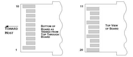
| Pin | Logic | Symbol | Description |
| 1 |
VeeT |
Module Transmitter Ground | |
| 2 | LVTTL-O |
Tx_Fault |
Module Transmitter Fault |
| 3 | LVTTL-I |
Tx_Disable |
Transmitter disable; Turns off transmitter laser output |
| 4 | LVTTL-I/O |
SDA |
2-wire Serial Interface Data Line (Same as MOD-DEF2 in INF-8074i) |
| 5 | LVTTL-I/O |
SCL |
2-wire Serial Interface Clock (Same as MOD-DEF1 in INF-8074i) |
| 6 |
Mod_ABS |
Module Absent, connected to VeeT or VeeR in the module | |
| 7 | LVTTL-I |
RS0 |
Rate Select 0, optionally controls SFP+ module receiver |
| 8 | LVTTL-O |
Rx_LOS |
Receiver Loss of Signal Indication (In FC designated as Rx_LOS and in Ethernet designated as Signal Detect) |
| 9 | LVTTL-I |
RS1 |
Rate Select 1, optionally controls SFP+ module transmitter |
| 10 |
VeeR |
Module Receiver Ground | |
| 11 |
VeeR |
Module Receiver Ground | |
| 12 | CML-O |
RD- |
Receiver Inverted Data Output |
| 13 | CML-O | RD+ | Receiver Non-Inverted Data Output |
| 14 | VeeR | Module Receiver Ground | |
| 15 | VccR | Module Receiver 3.3 V Supply | |
| 16 | VccT | Module Transmitter 3.3 V Supply | |
| 17 | VeeT | Module Transmitter Ground | |
| 18 | CML-I | TD+ | Transmitter Non-Inverted Data Input |
| 19 | CML-I | TD- | Transmitter Inverted Data Input |
| 20 | VeeT | Module Transmitter Ground |
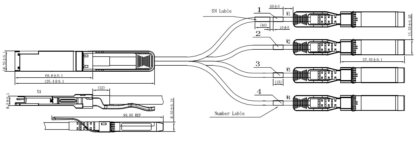
Mechanical Specifications
Regulatory Compliance
| Feature | Test Method | Performance |
| Electrostatic Discharge (ESD) to the Electrical Pins |
MIL-STD-883C Method 3015.7 |
Class 1(>2000 Volts) |
| Electromagnetic Interference (EMI) | FCC Class B | Compliant with Standards |
| CENELEC EN55022 Class B | ||
| CISPR22 ITE Class B | ||
|
RF Immunity (RFI) |
IEC61000-4-3 |
Typically Show no Measurable Effect from a 10V/m Field Swept from 80 to 1000MHz |
| RoHS Compliance | RoHS Directive 2011/65/EU and it's Amendment Directives 6/6 | RoHS 6/6 compliant |
Appendix A. Document Revision
| Version No. | Date | Description |
| 1.0 | 2018-3-1 | Preliminary datasheet |
Write your message here and send it to us
Related Products
More +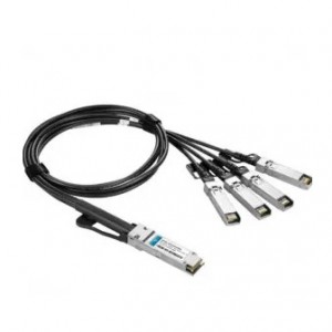
-

Phone
-

Skype
-

E-mail
-

Whatsapp
-

Top